

Raffay Sultan
Mubashir Rafique
https://urn.fi/urn:nbn:fi-fe20261012133636
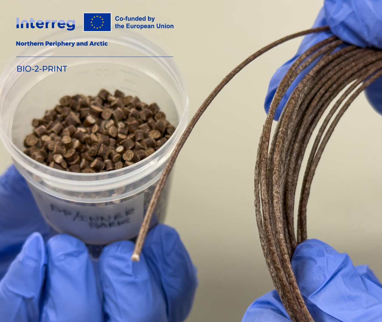
What if underutilized natural fibres could become useful raw materials for the next generation of 3D-printed products? In the BIO-2-PRINT project, materials such as inner bark and boat-industry wood waste are being transformed into fibre-reinforced polymer composites and processed into printable feedstock. The work shows how overlooked fibre resources can gain new value while supporting more circular and resource-efficient manufacturing.
Materials that are overlooked, discarded or left with little economic value may still have significant potential. By transforming underutilized natural fibres into polymer composite feedstock for 3D printing, the BIO-2-PRINT (Centria University of Applied Sciences 2026) project explores how local side streams can gain reducing dependence on virgin materials a new purpose while reducing dependence on virgin materials. The work demonstrates how material innovation can turn underutilized resources into practical solutions for a more circular future.
When an Underutilized Fibre Becomes a Resource
Natural fibres are present all around us, but not all of them enter productive material cycles. Such materials may therefore be discarded, burned for energy or directed towards relatively low value uses even though they still contain useful structural or chemical components. In the Northern Periphery and Arctic regions, these natural fibres arise from forestry, agriculture, marine environments, and industrial activities.
The BIO-2-PRINT project is investigating how such materials could be incorporated into new value chains. The project brings together partners from Finland, Ireland and Sweden aiming to develop value-added materials from underutilized fibres for 3D printing feedstock. Its broader objective is to contribute to a more circular and resource-efficient economy. (Interreg Northern Periphery and Arctic 2026.)
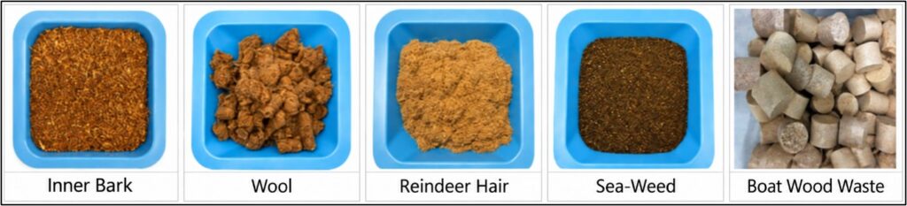
Among the fibres examined within the project are inner bark, wooden residues from the boat industry, seaweed, sheep wool and reindeer hair as shown in Figure 1. Screening is an important part of this work because not every discarded material will be suitable for a particular composite or manufacturing process. Project investigations have so far identified inner bark and boat-industry wood waste as particularly promising candidates for further composite development in regard to project goals.
Why Use Natural Fibres as Reinforcement in Polymer Composites?
This composite approach makes it possible to reduce the amount of polymer required while giving an underutilized fibre fraction a functional role in a new material.
A polymer provides the continuous matrix that allows a product to be shaped and processed, while natural fibres or particles can act as fillers or reinforcement. Depending on the fibre, polymer, formulation and processing conditions, natural-fibre-reinforced composites offer various advantages such as recyclability and useful mechanical properties. Natural fibres are therefore increasingly being investigated as alternatives to conventional fillers and reinforcements in sustainable polymer composites. (Ajayi, Rusnakova, Ajayi, Ogunleye, Agu & Amenaghawon 2025.)
Aside from various advantages, natural fibres present many technical challenges. Plant-based fibres, such as wood fibres are generally hydrophilic, while many commonly used thermoplastics are hydrophobic. This difference can result in poor adhesion between the fibre and polymer matrix. Fibre moisture, size, thermal stability, dispersion, and concentration can also influence processing parameters and final properties of a composite.
Therefore, the successful use of these materials involves more than simply combining fibres with a polymer matrix. The complete material system must be designed around the raw materials and the intended manufacturing process. Fibre treatments and additives can also be used to improve bonding between the fibre and polymer, helping to achieve better composite performance. (Ajayi et al. 2025.)
From Underutilized Fibre to Printable Composite
The work carried out at Centria has so far shown that inner bark and wood-based industrial waste have good potential as a fibre reinforcement in polymer composites. These materials were therefore preprocessed and incorporated into thermoplastic matrices as short-fibre reinforcements.
Composite formulations containing 30%, 40%, and 50% fibre content were successfully produced. Reaching these relatively high fibre contents was an important practical step and achievement as it significantly reduces the polymer fraction.
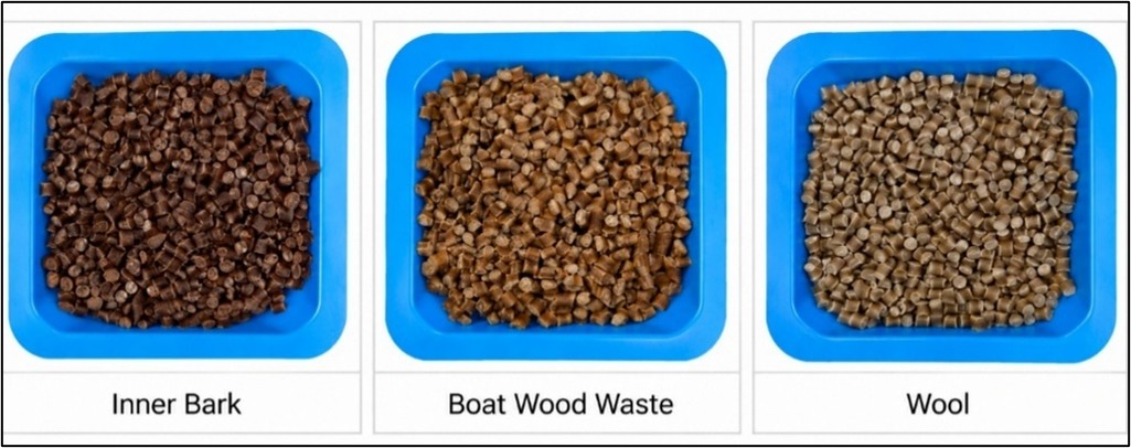
Producing pellets, as shown in Figure 2, is only one stage of developing a 3D-printing feedstock. The material must subsequently pass through an extrusion and printing process without excessive warpage, blockage, loss of dimensional control, and many other parameters. Natural-fibre-reinforced materials are particularly interesting in this respect because variations in fibre concentration and morphology can significantly influence key processing and performance characteristics, including melt flow, stiffness, mechanical strength and dimensional stability.
Research on additive manufacturing has increasingly examined natural-fibre-reinforced thermoplastic composites because they combine the design flexibility of 3D printing with the potential benefits of renewable reinforcement and reuseable polymer. Achieving reliable printability while maintaining useful properties remains one of the central research challenges. (Adjei-Yeboah & Jahan 2026.)
Printing in BIO-2-PRINT
In BIO-2-PRINT, FGF (Fused Granulate Fabrication) printing provides a practical link between material development and subsequent characterization. Each trial demonstrates how a composite formulation responds to the selected processing parameters and produces box-shaped structures for inspection and specimen preparation.
The printing workflow begins with the creation of a simple box-shaped model in CAD modelling software. The geometry is saved as a STEP file and imported into Aibuild (Aibuild n.d.), which is the software used to prepare the toolpath for the robotic printing system and extrusion output. At this stage, the model is sliced, and the principal printing parameters are defined. These include the bead width, printing speed, extrusion temperature, raft configuration, toolpath geometry, and other settings that determine how the material will be deposited.
Aibuild calculates the required robot movements and generates the production file for the printing system. The overall digital workflow is summarized in Figure 3.

Once the toolpath has been prepared and checked, the production file is transferred to the printing system. At Centria, the composite materials are printed using an ABB robot equipped with a CEAD E25 pellet extruder (CEAD 2026). The robot controls the movement of the extrusion nozzle, while the extruder melts the composite pellets and supplies material for deposition.
Before the full printing sequence begins, a small amount of material is extruded while the nozzle is away from the printing bed. This initial extrusion provides the first opportunity to assess the material. The flow should be continuous and regular to produce a stable bead. Pauses, pulsation or other irregularities may indicate unstable feeding or unsuitable processing conditions. A characteristic popping sound during extrusion may indicate that residual moisture remains in the material.
Once the initial flow has been confirmed, the nozzle moves towards the printing platform and begins depositing the first bead. Attention is given to the first layer because it forms the foundation for the structure above. The bead must maintain a suitable shape, remain adhered to the print bed, and provide a good surface for the following layers to have sufficient interlayer bonding. Once this is achieved, the print can be allowed to proceed. Otherwise, revisions are made at this initial stage. Figure 4 shows the type of box produced during these printing trials.
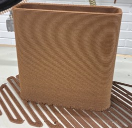
Selected parameters can also be adjusted manually through the operator interface during printing. These include the material constant, which affects the amount of material supplied by the extruder, speed of the robot, temperatures of the individual extruder zones, and the cooling applied to the deposited material. These controls allow the operator to respond directly to the material’s real-time behaviour during printing, reducing the need to interrupt the process and repeatedly revise the digital input parameters. To make the trials comparable, the main material and process settings are recorded for each print; an example is presented in Table 1.
Table 1. Example of the material and process parameters recorded for a robotic 3D-printing trial.
| Printing parameter | Value |
| Material formulation | PP45/MAPP5/BW50 (0.5 mm) |
| Nozzle temperature zones | 200 / 195 / 190 / 185 °C |
| Box dimensions, L × W × H | 310 × 100 × 320 mm |
| Corner radius | 30 mm |
| Nominal wall thickness | 10 mm |
| Layer height | 3 mm |
| Nozzle speed | 15 mm/s |
| Priming-line length | 300 mm |
| Raft offset from main geometry | 100 mm |
| Number of raft layers | 1 |
| Raft-layer thickness | 10 mm |
| Cooling | Off |
Monitoring continues throughout the printing process, where various indicators such as incomplete deposition, variations in bead width, flow interruptions, or rough surfaces may indicate that adjustments are needed.
Surface tearing or material pull-out can produce an uneven bead and result in bad adhesion. Some discontinuities may be visible during printing, whereas others may only become apparent after the printed structure has been cut and machined. CNC milling therefore serves both as a specimen-preparation method and as an additional opportunity to inspect the internal quality of a printed object.
Sections are cut from the printed walls and CNC milled to obtain specimens with controlled dimensions and surface conditions. Samples are prepared in the 0° and 90° directions relative to the principal printing direction. A specimen loaded along the deposited beads behaves differently from one loaded across bead or layer interfaces. The complete sequence from material formulation to testing and feedback is illustrated in Figure 5.
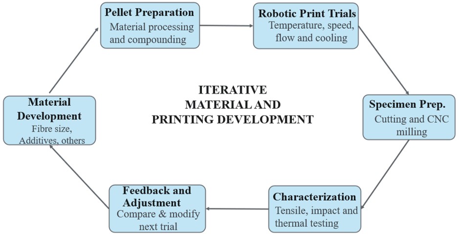
The printing and testing stages create a feedback loop for material development. Observations made during extrusion and deposition can indicate whether changes are needed in fibre size, fibre content, additives, compatibilizers, material preparation, or compounding conditions. Similarly, mechanical and thermal characterization can help determine whether a material that is being processed and printed is providing suitable performance or not.
The adjusted formulation can then be processed into pellets and returned to the printing stage for another trial. Printing parameters such as temperature, speed, cooling, material flow, and bead geometry may also be modified based on earlier observations. Material development and 3D printing are therefore not treated as separate activities within BIO-2-PRINT. Instead, they form an iterative process in which information from each material development, printing and testing stage guides the next cycle of work.
In this way, each printing trial is not only a test of the material, but also a step towards giving underutilized natural fibres a new and valuable role in future manufacturing.
Funding acknowledgement
This work was carried out as part of the BIO-2-PRINT project, funded through the Interreg Northern Periphery and Arctic programme.
References
Adjei-Yeboah, J. & Jahan, M. P. 2026. Additive manufacturing of natural fiber reinforced polymer composites – A review. Journal of Thermoplastic Composite Materials, 39(8), 4125–4205. Available at: https://doi.org/10.1177/08927057261415828. Accessed 11 September 2026.
Aibuild. n.d. AI for engineering. Available at: https://ai-build.com/. Accessed 14 September 2026.
Ajayi, N. E., Rusnakova, S., Ajayi, A. E., Ogunleye, R. O., Agu, S. O. & Amenaghawon, A. N. 2025. A comprehensive review of natural fiber reinforced polymer composites as emerging materials for sustainable applications. Applied Materials Today, 43, 102666. Available at: https://doi.org/10.1016/j.apmt.2025.102666. Accessed 11 September 2026.
CEAD. 2026. Pellet extruders for large scale 3D printing. Available at: https://ceadgroup.com/solutions/technology-components/. Accessed 14 September 2026.Centria University of Applied Sciences. 2026. BIO-2-PRINT. Available at: https://net.centria.fi/hanke/bio-2-print/. Accessed 11 September 2026.
Interreg Northern Periphery and Arctic. 2026. BIO-2-PRINT – From waste to worth: Building a value chain for underutilized natural fibres as feedstock in 3D printing. Available at: https://www.interreg-npa.eu/projects/bio-2-print/. Accessed 11 September 2026.
Raffay Sultan
RDI Expert
Centria University of Applied Sciences
p. 050 566 2787
Mubashir Rafique
RDI Expert
Centria University of Applied Sciences
p. 050 471 9394